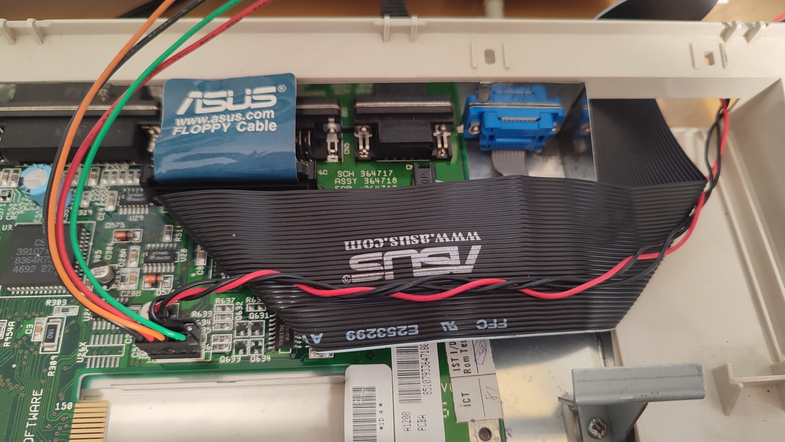
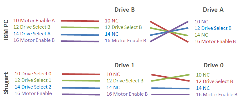
I replaced the internal drive of my Amiga 1200 with a Gotek drive. So far it works well. Now I wanted to place the drive outside of the case by extending the ribbon and power cable and routing the cables out the right rear panel. The original ribbon cable has 34 pins and there is a female IDC connector on both ends. So I went through my parts bin and found a floppy cable for a PC. It was just the right length. But why did it have a funny twist in it?
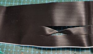
Something was wrong, since all the leads were connected straight through on the original cable. After a little research it turned out that PCs and the Amiga use the same cable and connector, but the pinouts are different. The PC uses an IBM standard. And the Amiga and many other retro computers use the Shugart standard:
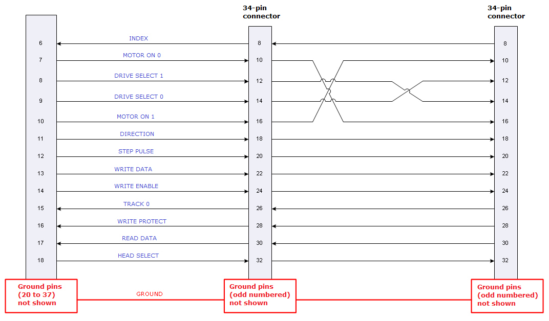
On a PC, if all lines are connected straight through, then the drive appears as drive B:. And if lines 10/16 and 12/14 are swapped, then the drive appears as drive A:. So I had a cable with only one end which was used for a floppy as drive A:.
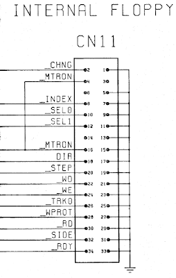
Shugart uses a similar technique to select a drive with the lines sel0 (pin 10) and sel1 (pin 12). Here it is also possible to switch the drive assignment with a twist in the cable. This page from ByteDelight has a nice diagram:
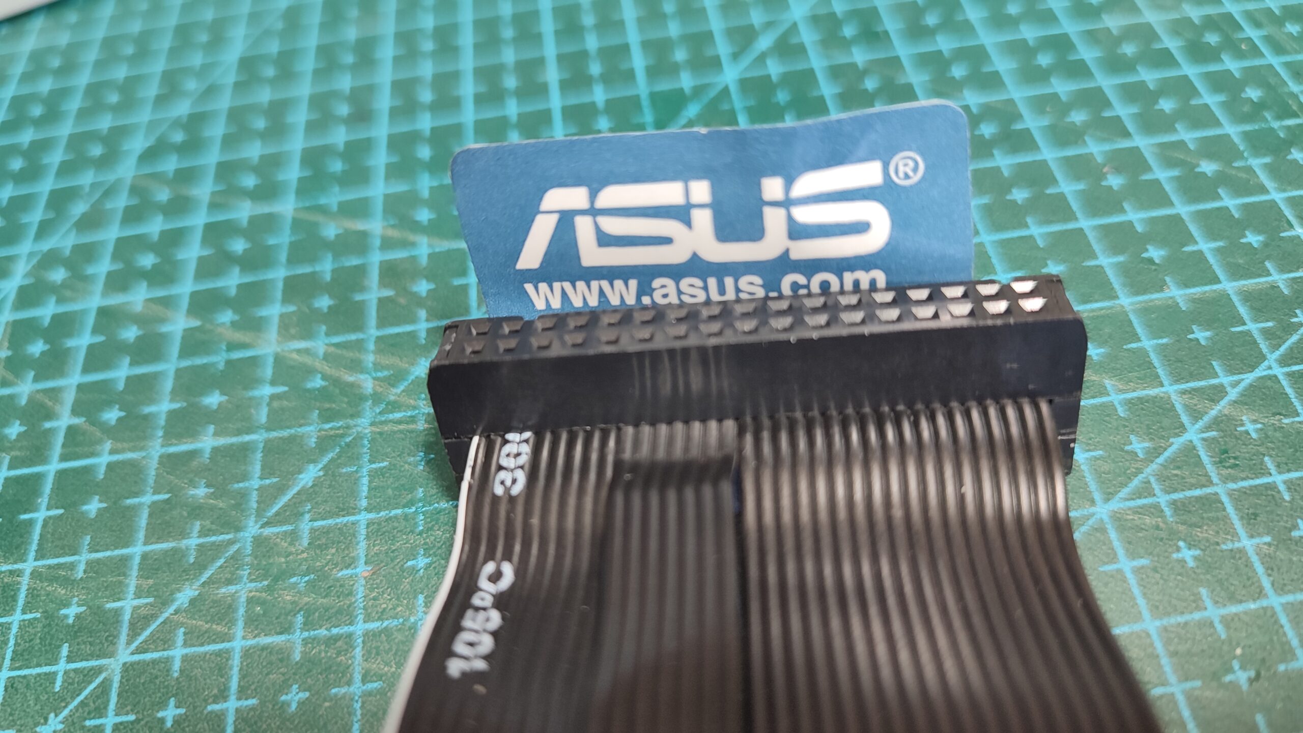
Since the twisted pins are different in both standards, the cable was no good to me in it’s current form. I had enough ribbon cables to manufacture an new cable, but I was missing 34 pin IDC connectors. So I tried to take the connector of the PC floppy cable apart. I’ve done this before, and usually the clips on the sides of the connector break. But I was careful and only one of the four clips broke. Then I untwisted the cable and put it back together. I glued the broken clip with super glue.

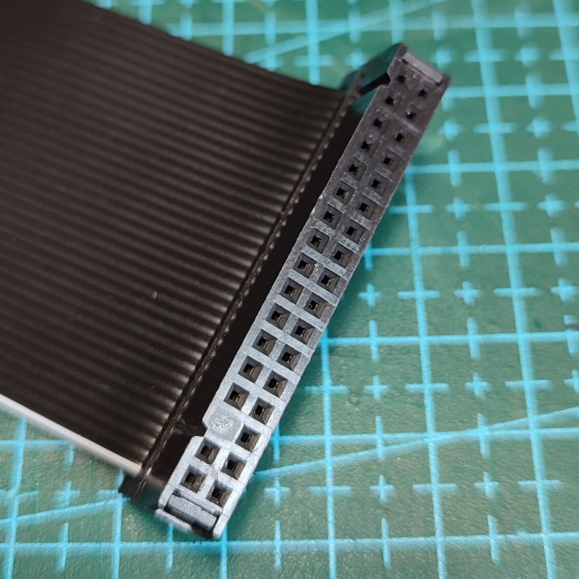
Then there was another small hurdle. Pin 5 was blocked on one of the connectors. This is to prevent the connector from being connected incorrectly. But on the Amiga the blocked pin is pin 3. So I just drilled out the blocked pin.
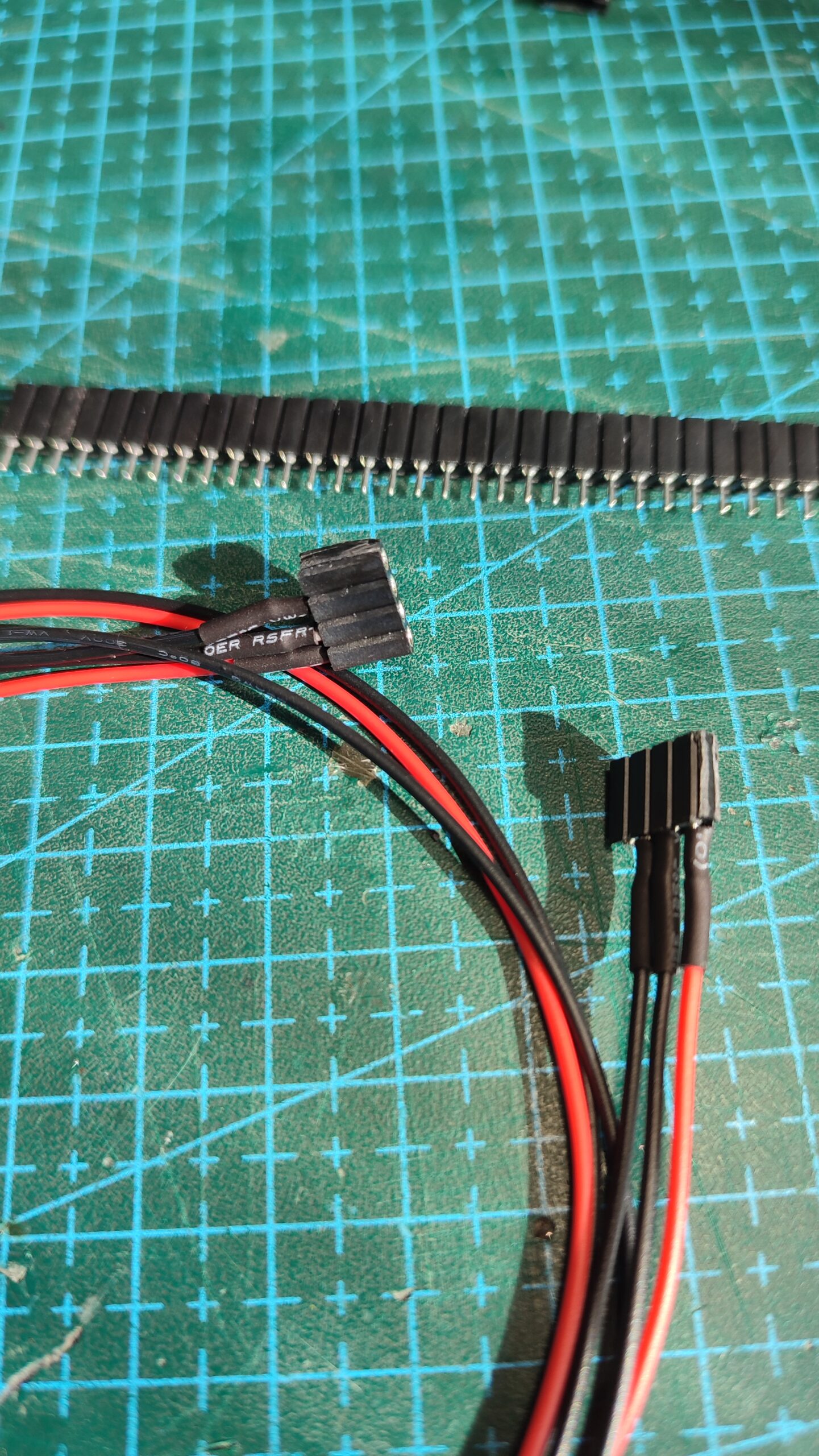
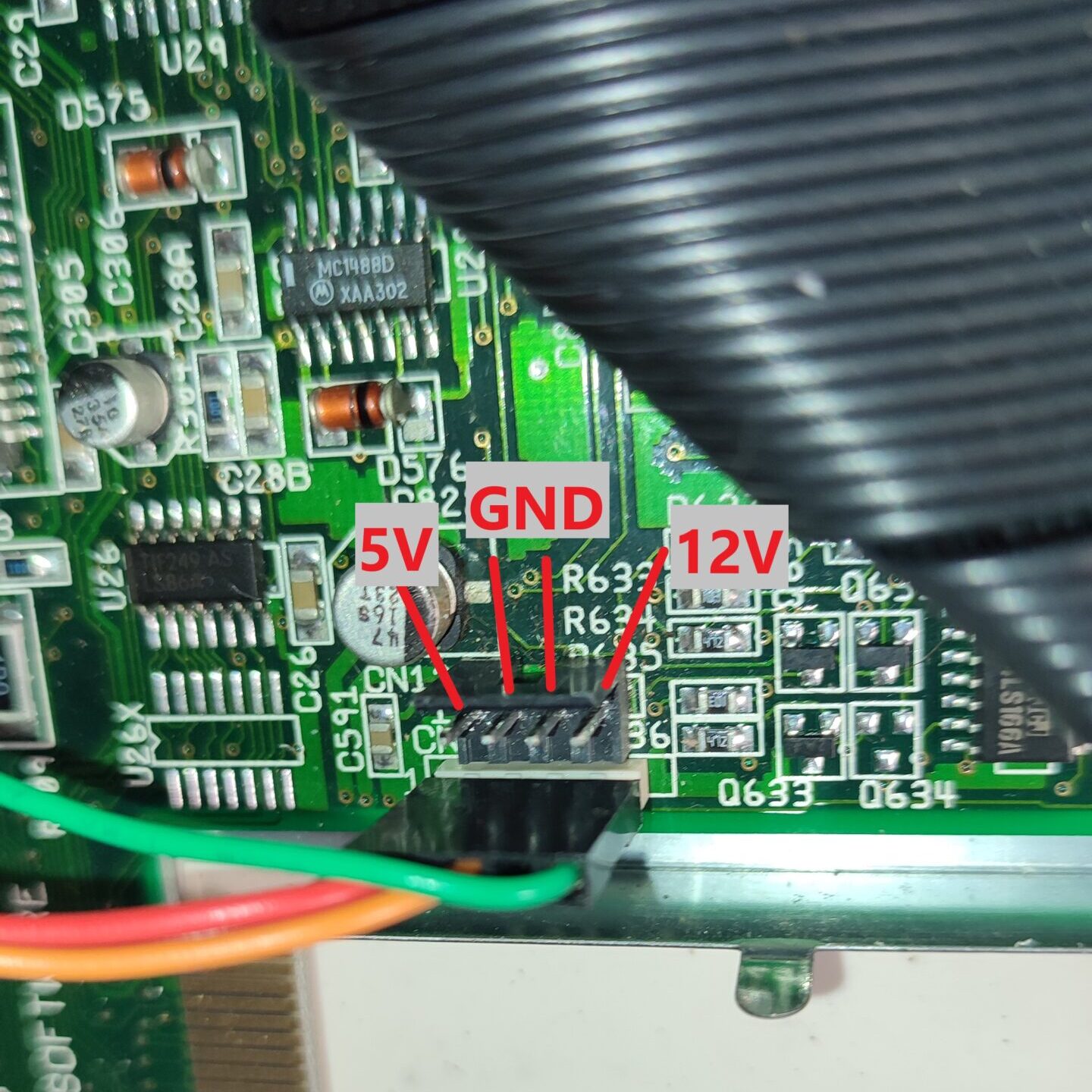
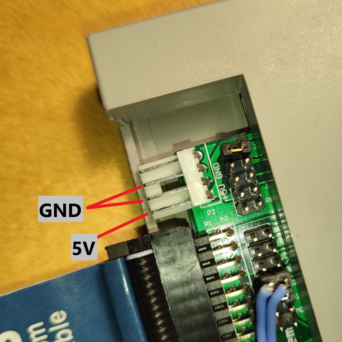
Now that the ribbon cable was sorted, all that was left to do was to fabricate a longer power cable. I could have cut the cable from the original connector and lengthened the wire. But I wanted to keep it in it’s original form. So I just soldered wires to standard 0.1″ pin headers. I left out the 12V wire as it is not needed for the Gotek. I have to be careful when connecting the cable, since the pin header won’t protect me to plug in the cable the wrong way around unlike the original connector.
And that’s it. I routed the cables out the back port. Now it was time to play a nice game.